In today’s connected world, building low-power wireless devices is essential for applications ranging from remote sensors to smart automation. Antennino is one such tool — a tiny yet powerful Arduino-compatible board that combines ultra-efficient computing, flexible communication options, and real-world adaptability for Internet of Things (IoT) applications.
This comprehensive guide dives deep into everything you need to know about Antennino — from core hardware and power management to wireless communication, real-world use cases, comparisons with other boards, and future possibilities.
What is Antennino?
Antennino is a compact, Arduino-compatible board designed for low-power wireless communication. Its name comes from merging “Antenna” and “Arduino”, reflecting its purpose: an Arduino-based microcontroller equipped with wireless communication capabilities.
Unlike traditional Arduino boards that require separate modules for wireless communication, Antennino integrates the core hardware to handle RF transmission, energy-efficient processing, and connectivity — all while maintaining ease of use within the Arduino ecosystem.
The Meaning Behind the Name
- “Antenna” signifies its communication focus.
- “-ino” reflects its roots in the Arduino ecosystem — small, versatile, and accessible.
Together, Antennino promises a user-friendly platform for building devices that communicate wirelessly while consuming minimal energy.
Why Antennino Was Created
Antennino emerged to solve key challenges in IoT design:
- Battery efficiency: Many remote IoT nodes run on battery power. Extending battery life increases reliability and reduces maintenance.
- Simplified wireless design: Pre-integrated RF and antenna hardware eliminate the need for external modules.
- OTA updates: Over-the-air programming enables firmware updates without physically accessing the device.
How It Differs from a Standard Arduino Board
| Feature | Antennino | Standard Arduino Uno/Nano |
|---|---|---|
| Wireless Communication | Built-in RF (433 MHz or variants) | Requires external module |
| Power Efficiency | Ultra-low power designs with deep sleep | Standard power use |
| OTA Firmware Updates | Supported | Not natively supported |
| Battery Operation | Designed for long-term battery use | General-purpose |
| Ideal For | IoT & remote nodes | Prototyping and general projects |
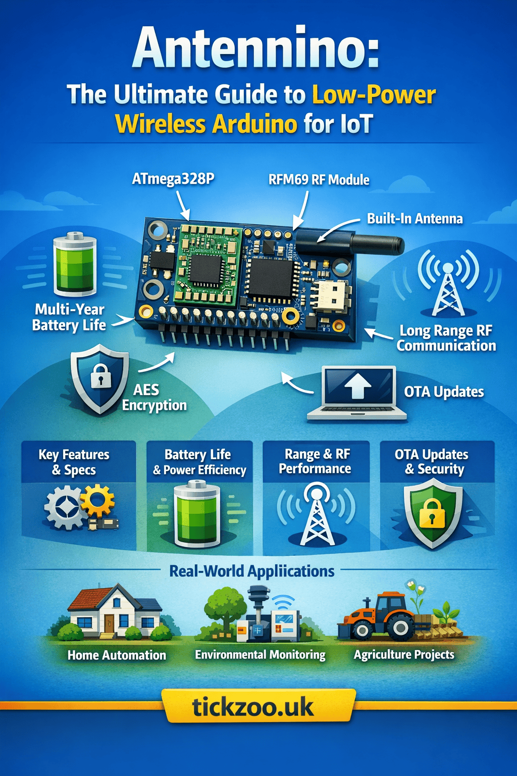
Core Hardware Architecture of Antennino
Antennino blends familiar microcontroller technology with low-power and wireless components. The key elements are engineered for flexibility, energy management, and communication.
ATmega328P Microcontroller (PicoPower Technology)
At its heart, Antennino uses the ATmega328P, a microcontroller widely recognized from Arduino Uno and Nano boards. It’s chosen for its:
- Low power consumption via PicoPower technology
- Compatibility with Arduino IDE
- Rich ecosystem of libraries
- Adequate flash, SRAM, and I/O capabilities
This ensures that existing Arduino code can be reused for Antennino projects with minimal adaptation.
RFM69 433MHz Wireless Transceiver with AES Encryption
Wireless communication is delivered by the RFM69 module — a compact RF transceiver operating at 433 MHz (other frequency variants can be used depending on region and module). Key benefits include:
- Low power communication
- Hardware-level AES encryption for secure data
- Automatic Transmission Control (ATC) to manage power during transmission
- Integrated antenna connection (via U.FL or direct solder)
This allows Antennino to communicate reliably over moderate ranges, with encryption usable for secure IoT use cases.
Built-in Flash Memory for Data Logging & OTA
Unlike many microcontroller boards, Antennino includes onboard Flash memory, offering:
- Local data logging for sensor readings
- Storage for OTA (Over-The-Air) updates
- Space for firmware staging
This enhances Antennino’s ability to operate autonomously in the field and receive updates without physical access.
Grove Connectors and Expandability
Antennino includes four Grove connectors — standardized ports for adding sensors and modules. These can support:
- RS232
- I²C
- Analog input
- Digital GPIO
Grove connectors simplify hardware expansion without soldering.
OLED Display Integration (I²C Interface)
A small OLED display can be directly mounted on the board using I²C communication. These displays are ideal for:
- Debugging output
- Visual feedback
- Local status monitoring
Internal Sensors (DS18B20 & LDR)
Antennino boards often come with:
- DS18B20 temperature sensor for accurate readings
- Light Dependent Resistor (LDR) for ambient light measurement
These built-in sensors make it easy to begin using Antennino without additional hardware.
Advanced Low-Power Design Explained
One of Antennino’s most compelling features is its energy management, enabling extended battery life — often measured in years rather than hours or days.
ATmega328P Sleep Modes & Watchdog Timer (WDT)
Microcontrollers support various sleep modes:
- Idle State: CPU stops, peripherals may continue running
- Power-down: Deepest sleep, only external interrupts wake the system
- Standby: Allows faster wake-up with limited peripheral activity
With the Watchdog Timer (WDT), Antennino can periodically wake up, complete tasks, and return to sleep, dramatically reducing energy use.
External Timer Strategy Using TPL5110 (35nA Standby)
Instead of relying solely on the microcontroller’s internal timers, Antennino uses the TPL5110 low-power timer chip:
- Consumes as little as 35 nA
- Controls power gating via a PMOS transistor
- Powers the board only when action is needed
- Supports programmable intervals up to 2 hours
This circuit strategy prevents the microcontroller from consuming power while idle, achieving minute or even nanamp standby currents.
Power Gating with PMOS Control
Transistors controlled by GPIO pins are used to cut power to:
- External sensors
- ADC circuits
- Communication modules
- Peripherals not in use
By isolating these hardware blocks, the system draws only what’s absolutely required.
Disabling Peripherals for Maximum Efficiency
Peripherals such as analog converters, serial interfaces, and radios can be turned off or put to sleep via firmware, conserving energy.
Real Battery Life Calculations (With Formula Examples)
The real measure of energy efficiency is autonomy, calculated using:
Battery Life (hours) = (C × efficiency factor) / average current
For example:
- C = 2400 mAh (2 × AA batteries)
- Average active current = 40 mA
- Standby current = 35 nA
- Efficiency factor = 0.85 (accounts for regulator losses)
Using accurate advanced formulas that include sleep/awake cycles, this can translate into multi-year operation — often 3–4 years or more for periodic sensing tasks.
Power Supply Options & Configuration Jumpers
Antennino supports flexible power supply choices, which affect both operation and energy use.
AA Battery Mode with MAX856 Switching Regulator
For battery-powered use, Antennino includes:
- Support for two 1.5 V AA batteries (alkaline or rechargeable)
- A MAX856 switching regulator which:
- Accepts input from 0.8 V up to 3.3 V
- Output: stable 3.3 V
- Low quiescent current (phantom load ~25 µA)
- Efficient conversion for longer life
External 3.6–12V Power Mode
Antennino can be powered from a broader voltage source through a linear regulator (MCP1703). This mode is ideal when battery isn’t used or when driven by a main power supply.
Direct 3.3V Supply Mode (No Regulator)
For systems with a regulated 3.3V supply (such as directly from solar or another controller), Antennino bypasses onboard regulators for maximum efficiency.
Selecting Jumpers (J1, J2, J3, J4 Explained)
Antennino uses board jumpers to select:
- Which power source is active
- Whether the external timer (TPL5110) is used
- Whether onboard regulators are bypassed
- Battery vs external vs direct supply
Proper jumper settings can significantly affect power performance and should be configured based on your use case.
Best Configuration for Ultra-Low Power Projects
For longest battery life:
- Use onboard battery supply
- Enable TPL5110 timer-based power gating
- Disable unused peripherals in firmware
- Use deep microcontroller sleep modes
Wireless Communication Capabilities
Antennino’s core strength lies in its ability to send and receive data wirelessly without external modules.
433 MHz RF Communication Explained
The RFM69 transceiver enables:
- Reliable communication at 433 MHz
- Moderate range (hundreds of meters to kilometers depending on antenna)
- Low power consumption during transmission
- Support for both simple point-to-point and networked communication topologies
AES Hardware Encryption for Secure Data
Security is essential, especially for IoT in critical applications. The RFM69 module supports hardware-based AES encryption, keeping transmissions secure without costing CPU cycles.
Automatic Transmission Control (ATC)
ATC dynamically adjusts transmit power based on signal conditions, minimizing energy usage during radio transmission while maintaining reliable communication quality.
Range Optimization Techniques
Range depends on several factors:
- Antenna design and placement
- Environmental interference
- Transmit power level
- Receiver sensitivity
Using proper antennas and line-of-sight, ranges of several hundred meters are easily achievable; with directional or external antennas, longer distances become possible.
Antenna Design (¼ Wave vs ½ Wave)
The wavelength (λ) for 433 MHz is approximately 69.2 cm. Typical antenna choices include:
- ¼ wave (~16.4 cm) — best balance of size and performance
- ½ wave (~32.9 cm) — longer, higher gain
- External antennas via U.FL connectors — for greater range and modularity
Choosing the right antenna type is critical for maximizing transmission distance.
Using External U.FL Antennas for High Gain
Antennino’s U.FL connector enables plugging in high-gain or tuned antennas, boosting range and signal stability for remote or industrial deployment.
Over-The-Air (OTA) Programming Explained
Updating hundreds of remote devices used to require physical access and manual intervention. Antennino simplifies this with built-in OTA programming support.
How OTA Works in Antennino
Antennino uses its wireless module and onboard flash to:
- Receive firmware updates from a gateway
- Store the new firmware in flash memory
- Validate and execute the update
This process avoids physical device access, saving time and deployment cost.
Flash Memory Usage for Remote Updates
Local flash memory ensures reliable OTA since code is stored and validated before activation, reducing the risk of bricking devices during update.
Benefits for Remote IoT Deployments
- No site visits needed for updates
- Rapid bug fixes and feature rollouts
- Centralized control from a gateway
- Scales well for large sensor networks
Real-World Applications of Antennino
Antennino’s blend of features makes it ideal for multiple real-world scenarios.
Smart Home Automation Systems
Build your own motion sensors, light controllers, door/window monitors, or environmental sensors that wirelessly report status to a central controller.
Smart Farming & Agricultural Monitoring
Antennino works for soil moisture sensors, weather stations, livestock tracking, and irrigation control — extending battery life across seasons.
Environmental Monitoring Stations
Measure air quality, temperature, humidity, water level, and more in locations with no internet or mains electricity.
Industrial IoT & Remote Data Logging
Deploy sensors in warehouses, factories, or open fields to log equipment status or environmental conditions, all without wires.
Wireless Robotics & Control Systems
Robots, drones, and mobile IoT platforms can exchange telemetry or commands using Antennino’s wireless link.
Smart City Infrastructure Projects
Streetlight controllers, parking sensors, public environmental monitors — all benefit from long-range, low-power communication.
Antennino vs Other Popular Development Boards
Understanding how Antennino compares with other boards helps clarify its niche.
| Feature | Antennino | Arduino Nano | ESP32 | Raspberry Pi Pico |
|---|---|---|---|---|
| Wireless | Built-in RF | External radio | Wi-Fi & BT | None |
| Power Efficiency | Ultra high | Low/moderate | Moderate | Low |
| OTA Support | Yes | No | Limited | No |
| Ideal Use | Remote IoT | Prototyping | Wi-Fi IoT | General use |
| Range | Long (RF) | Depends | Medium (Wi-Fi) | N/A |
Antennino fills a unique niche — it’s neither a full microcomputer nor a high-power Wi-Fi board, but rather a dedicated low-power wireless IoT controller.
Advantages of Antennino
- Ultra-Low Power Consumption: Multi-year battery life.
- Integrated Wireless Communication: Built-in RF removes the need for external modules.
- Open-Source Ecosystem: Arduino compatibility and community support.
- Secure Communication: AES encryption at hardware level.
- Flexible Power Options: Multiple configurations depending on deployment.
- OTA Updates: Future-proof remote updates without access.
Limitations & Challenges
While Antennino is a powerful tool, it’s not perfect for every use case.
Memory Constraints
The ATmega328P has limited flash/SRAM compared to faster microcontrollers, which can be a constraint for complex applications.
Processing Power Limits
Tasks like advanced AI processing, image recognition, or large data handling exceed its capabilities.
RF Interference
RF communication can be affected by obstacles, metal, or interference from other devices, requiring careful placement and antenna choice.
Learning Curve for Power Optimization
While Arduino makes programming easy, achieving ultra-low power operation requires thoughtful design and careful coding.
Antennino Circuit Overview (Simplified Explanation)
To use Antennino effectively, understanding basic hardware connections helps.
SPI Bus and Peripheral Access
The RFM69 wireless module, flash memory, and other peripherals communicate via the SPI bus (MOSI, MISO, SCK), controlled by chip select pins.
Interrupt Lines and Pin Allocation
External interrupts handle:
- Sensor triggers
- Wireless packet signals
- Wake-up events
Proper interrupt configuration allows efficient sleep/wake cycles.
Power Gating Circuit
PMOS transistors controlled by microcontroller pins enable cutting power to internal sensors when idle.
External Wake-Up Logic
Optoisolators and external hardware can trigger Antennino awake for interrupts, providing flexibility in how remote events are handled.
Step-By-Step: How to Build a Basic Antennino IoT Node
Here’s a quick practical example to help you start.
Required Components
- Antennino board
- DS18B20 temperature sensor (built-in)
- Grove peripherals (optional)
- External antenna (recommended)
- AA battery pack or external supply
Wiring Overview
- Mount the antenna via the U.FL connector or solder appropriate wire.
- Connect optional sensors via Grove ports.
- Set jumpers for power configuration (battery + regulator + timer).
- Power the board and connect via USB if needed.
Sample Arduino Sketch
#include <SPI.h>
#include <RFM69.h>
#include <Wire.h>

// Add libraries for sensors and RF

void setup() {
  // Initialize serial
  Serial.begin(9600);
  // Initialize RF
  // Initialize sensors
}

void loop() {
  // Read temperature
  // Send via RF
  // Go to sleep
}
Sending Data to a Gateway
Configure a gateway (such as Raspberry Pi with RFM69) to receive packets based on matching network IDs and encryption keys.
Frequently Asked Questions (SEO Gold Section)
Is Antennino better than Arduino for IoT?
Yes — if your project requires wireless connectivity and ultra-low power consumption.
What is the battery life of Antennino?
Depending on configuration and duty cycle, battery life can exceed 3 years on two AA cells.
Can Antennino connect to Wi-Fi?
Not natively, but external modules can be added for hybrid connectivity.
What frequency does Antennino use?
Commonly 433 MHz, but different regional modules (e.g., 868 MHz, 915 MHz) can be used depending on regulations.
How far can Antennino transmit data?
With proper antenna and line-of-sight, ranges of hundreds of meters to several kilometers are achievable.
Is Antennino suitable for industrial use?
Yes, especially for remote monitoring and automation where wired infrastructure isn’t feasible.
The Future of Antennino & Low-Power Wireless IoT
Antennino represents a class of tools growing in importance as IoT proliferates:
- LoRaWAN and long-range protocols will expand communication reach.
- Cloud connectivity will allow real-time dashboards and analytics.
- Edge intelligence may bring small-scale machine learning to tiny devices.
- Modular add-ons such as GPS, BLE, and cellular links could make Antennino even more versatile.
The trend toward sustainability, minimal maintenance, and high uptime ensures devices like Antennino continue to grow in relevance.
Final Verdict – Is Antennino Worth It in 2026?
In a world where connectivity and efficiency matter, Antennino delivers a unique balance of low-power operation, wireless communication, secure data handling, and Arduino compatibility.
Whether you’re a hobbyist, student, researcher, or professional engineer building remote sensors or automated networks, Antennino offers a compelling, cost-effective, and scalable platform — all without sacrificing simplicity.